|
Rotating Equipments
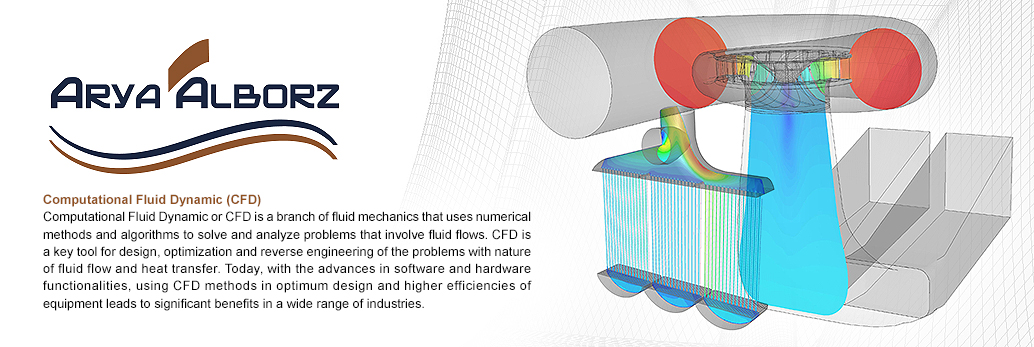
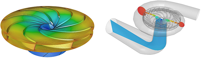
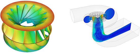
Comprehensive CFD Simulation
of a 260 MW
Pump-Turbine in
Pump Mode
Operation.
This project was
performed in
2011 to identify
the effect of
geometric
variations and
operational
conditions on
hydraulic
performance with
the aim of
reverse
engineering. Atos 3D scanning
equipment was
used to create a
precise cloud
point of runner.
Using the
drawings, the 3d
geometries of
spiral case,
stay vanes,
guide vanes,
draft tube and a
complete model
of hydraulic
pump was
created. After a
professional
structured mesh
generation for
runner, spiral
case and draft
tube, the effect
of operating
conditions on
hydraulic
efficiency,
head, runner
torque,
cavitaion and
other parameters
were studied.
Because of
discrepancy in
runner geometry
between model
test and
prototype, the
effects on
hydraulic
parameters and
power plant
efficiency was
comprehensively
studied.
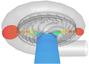 |
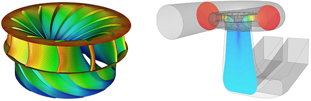
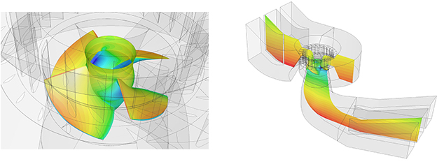
Comprehensive CFD Simulation
of a 260 MW
Pump-Turbine in
Turbine Mode
Operation
This project was
performed to
identify the
effect of the
geometric
variations and
operational
conditions on
the hydraulic
performance with
the aim of
reverse
engineering in
2011. Atos 3D
scanning
equipment was
used to create a
precise cloud
point of runner.
Using the
drawings, the 3d
geometry of
spiral case,
stay vanes,
guide vanes,
draft tube and a
complete model
of hydraulic
turbine is
created. After a
professional
structured mesh
generation for
runner, spiral
case and draft
tube, the effect
of operating
conditions on
hydraulic
efficiency,
head, runner
torque,
cavitaion and
other parameters
were studied.
Because of
discrepancy in
runner geometry
between model
test and
prototype, the
effects on
hydraulic
parameters and
power plant
efficiency were
comprehensively
studied.
 |
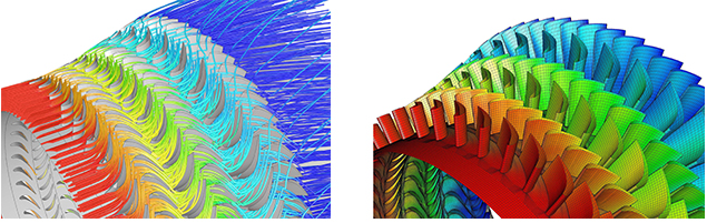
Comprehensive CFD and FEM
Simulation of a
Three Stages 4
MW Solar Centaur
Gas Turbine
This project was
executed in 2009
to identify the
potential of
improvements.
Atos 3D scanning
equipment was
used to create a
precise cloud
point of three
stages rotor and
stator. Using
cloud points, a
complete solid
model of a three
stages gas
turbine
including two
stages
compressor
turbine and one
stage power
turbine was
created.
Compressor
turbine and
power turbine
have different
shafts and
rotational
speeds. After
structured mesh
generation with
fine elements
for precise
boundary layer
simulation,
fluid flow and
heat transfer
were studied for
the entire of
three stages
turbine. Because
of difference in
the number of
blades in rotor
and stator of
three stages and
the
impossibility of
producing a
periodic sector,
regardless of
any
simplification
and assumptions
the CFD
simulations were
executed for the
entire domain
using parallel
high speed
computers. Using
pressure and
temperature
distribution on
blades, non
linear FEM
simulations to
study the Von
Mises stresses
on three stages
of rotor and
stator were
executed. After
a comprehensive
analyses of the
turbine using
CFD and FEM
simulations,
different
scenarios for
optimization
were widely
studied.
 |
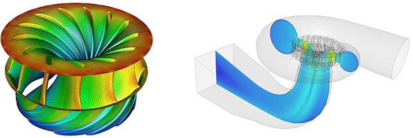
Comprehensive CFD and FEM
Simulation of a
250 MW Francis
Turbine
This project was
performed with
the aim of
reverse
engineering in
hydraulic
Francis turbine
design in 2008.
Atos 3D scanning
equipment was
used to create a
precise cloud
point of runner.
Using the
drawings, the 3d
geometry of
spiral case,
stay vanes,
guide vanes,
draft tube and a
complete model
of hydraulic
turbine was
created. After a
professional
structured mesh
generation for
runner, spiral
case and draft
tube, the effect
of operating
conditions on
hydraulic
efficiency,
head, runner
torque,
cavitaion and
other parameters
were studied.
After a
comprehensive
simulation of
hydraulic
turbine, the
effect of some
geometric
optimization
such as draft
tube length
reduction on
hydraulic
efficiency and
power plant
operation was
carried out.
 |
Comprehensive CFD and FEM
Simulation of a
250 MW Francis
Turbine with
X-Blade Design
This project was
performed in
2008 with the
aim of reverse
engineering in
hydraulic
Francis X-blade
turbine design
and geometric
optimization of
runner to fix
the cracks and
the effects on
power plant
hydraulic
efficiency. Atos
3D scanning
equipment was
used to create a
precise cloud
point of runner.
Using the
drawings, the 3d
geometry of
spiral case,
stay vanes,
guide vanes,
draft tube and a
complete model
of hydraulic
turbine was
created. Due to
cracks growing
on runner
blades, CFD
simulations for
Speed no load
and Load
rejection
condition were
also studied.
The pressure
distribution on
runner blade for
different
conditions were
used for FEM
analysis. After
designing
failure
detection,
various
modifications on
blade profiles
and thicknesses
were carried out
using coupled
CFD and FEM
simulations.
Finally the best
runner with high
hydraulic
performance and
sufficient
strength was
designed.
 |
Comprehensive CFD and FEM
Simulation of a
8 MW Francis
Turbine
This project was
performed in
2010 with the
aim of reverse
engineering in
hydraulic
Francis turbine
design and
benchmarking for
small hydraulic
power plant
potentials in
country. Atos 3D
scanning
equipment was
used to create a
precise cloud
point of runner.
Using the
drawings, the 3d
geometry of
spiral case,
stay vanes,
guide vanes,
draft tube and a
complete model
of hydraulic
turbine was
created. After a
professional
structured mesh
generation for
runner and draft
tube, the effect
of operating
conditions on
hydraulic
efficiency,
head, runner
torque,
cavitaion and
other parameters
were studied.
Based on CFD
results, the
pressure
distribution on
runner was used
for
comprehensive
FEM simulations.
 |
Comprehensive CFD Simulation
of a 100 MW
Kaplan Turbine
This project was
performed in
2010 with the
aim of reverse
engineering in
Kaplan hydraulic
turbine design.
Using the
drawings, the 3d
geometry of
spiral case,
stay vanes,
guide vanes,
draft tube,
runner and a
complete model
of hydraulic
turbine was
created. After a
professional
structured mesh
generation for
spiral case and
draft tube, the
effect of
operating
conditions on
hydraulic
efficiency,
head, runner
torque,
cavitaion and
other parameters
were studied.
 |
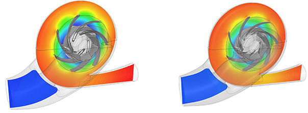
Comprehensive CFD Simulation
of Two BB1 API
610 hydraulic
pumps
This project was
performed in
2012 with the
aim of
evaluating the
efficiency of
two hydraulic
pumps. After the
identification
of reasons for
the lower
efficiency in
one of them,
some innovative
techniques for
optimization on
both of them
were found out.
Atos 3D scanning
equipment was
used to create a
precise cloud
point of two
impellers and
volutes. Then
complete models
of two hydraulic
pumps were
created. After a
professional
structured mesh
generation for
impellers with
boundary layer
growth, CFD
simulations were
executed.
Because of 10%
lower head in
one of the
pumps, losses at
different
sections were
compared.
According to the
results,
critical
sections were
found out so
that with lowest
geometric
modifications of
molds, the most
effectiveness on
hydraulic
efficiency was
achieved.
 |
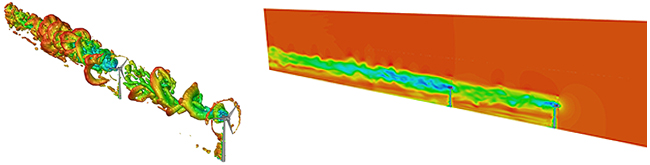
Comprehensive CFD Simulation
of Wind Farm
Considering the
Wake Effect of
Upstream
Turbines
These studies
were performed
with the aim of
producing a deep
insight into the
design of wind
farms and wake
effect of
upstream
turbines on
plant
efficiency. In
this study a
domain with two
200 KW wind
turbines were
simulated. The
second turbine
was placed in
different
locations
compare to the
first turbine to
study the wake
effect.
Comprehensive
CFD simulations
at different
wind speeds and
wind turbine
rotational
speeds were
performed and
torque and power
were widely
studied. Due to
the significant
reduction in
power generated
in the
downstream
turbines,
producing
software for
optimum wind
farms design
with the
consideration of
wake effects has
been started in
Arya Alborz
Company.
|